STEP1: Confirm and perform wiring Position Feedback Signal Connector CN5 (for Full-closed Control) The servo drive can be connected to a linear encoder or external encoder to constitute a full-closed loop via this position feedback signal connector CN5. In position mode, the pulse position commands given by the external controller just refer to the control loop structure of the external linear encoder. Please refer to Chapter 6 for more description.
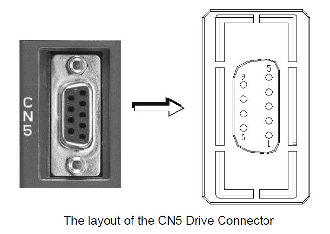
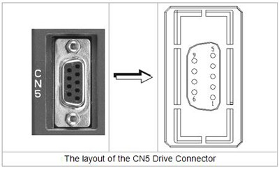
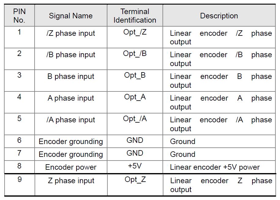
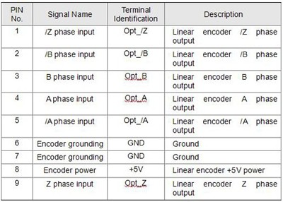
CN5 Terminal Signal Identification
STEP2: Check if the servo drive is not in the full-closed control mode (check if the full-closed control function is disabled). Parameter P1-74: Enable/Disable full-closed control function. This parameter is used to determine the function of full-closed control.
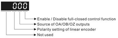
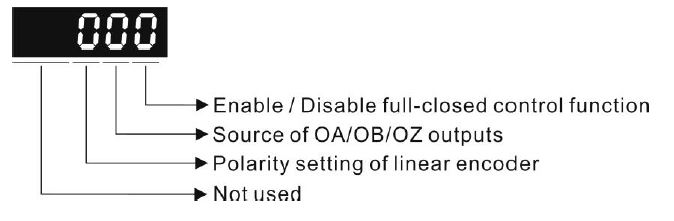
Please note that before using the full-closed control function, the full-closed control function selection of P1-74 must be set to 0.
STEP3: Activate ASDA-Soft configuration software and set P1-72 to 80000. Parameter P1-72: How many pulses will be sent from the linear encoder referring to one turn of the servo motor.
STEP4: Enable Data Scope function, a PC-based digital oscilloscope function of the ASDA-Soft configuration software. Select two channels, Motor feedback pulse number (encoder unit, 1280000 pulse/rev) and external encoder feedback pulse number (The data length of these two channels are both 32-bit).
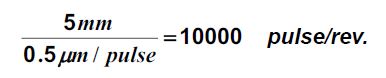
STEP5: Use the Data Scope function to measure the feedback pulse number sent from the linear encoder referring to one turn of the servo motor. If a ball screw is used, the customer will provide the pitch of the ball screw and the resolution of the linear encoder. When the pitch of ball screw is 5mm and the resolution of the linear encoder is 0.5um/pulse, the feedback pulse number sent from the linear encoder for one turn of the servo motor should be

pulse/rev.
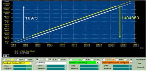
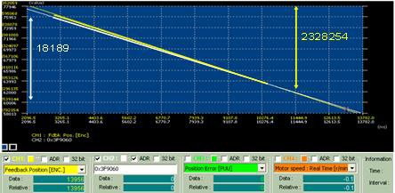
Set the servo drive for servo on and use the JOG function to control the servo to move in one direction at low speed safely. At this time, you will see data as in the following Figure 1.

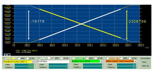
In the above figure, for one turn of travel, the traveling distance of the motor encoder is 2326786 pulses and the traveling distance of the linear encoder is -18178 pulses. The linear encoder feedback pulse numbers for one turn traveling is equal to:


If the customer does not know the pitch of the ball screw, please use the above equation to measure the linear encoder feedback pulse number for one turn of the servo motor.
If the customer knows the pitch of the ball screw, please use the above equation to check if the linear encoder feedback pulse number for one turn of the servo motor is correct.
STEP6: In Figure 1, you will find that the directions of both pulse trains are in reverse. One is positive and the other is negative trend. If not, set the polarity setting of the linear encoder of P1-74 to 1 for reversing the direction of motor encoder pulses from the linear encoder. You will then see both trends of the pulse trains are in the same direction (see Figure 2).
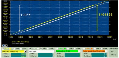
Please control the servo motor to run in the forward and reverse directions and ensure that the feedback pulse numbers in the forward and reverse directions are both correct.
When the pulse direction is a positive trend, the measured linear encoder feedback pulse number for one turn of the servo motor is about 10000 and the pulse trains increase in the same direction.
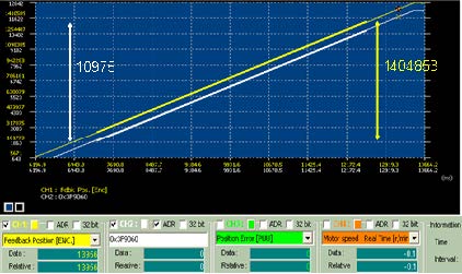
When the pulse direction is a negative trend, the measured linear encoder feedback pulse number for one turn of the servo motor is about 10000 and the pulse trains decrease in the same direction.
STEP7: If the specification of your mechanism is already known, the customer can use P1-72 to count the linear encoder directly. If the specification of your mechanism is not known, the customer can use the PC data scope function to simulate the specification of your mechanism first and use P1-72 to count the linear encoder directly.
STEP8: After P1-72 is set, use P1-74 to determine the polarity setting of the linear encoder and then enable the full-closed control function.
Note: When the full-closed control function is enabled, the electronic gear ratio will refer to the command resolution of the linear encoder instead of the motor encoder. For example, when P1-44 and P1-45 are both set to 1 (the electronic gear ratio is set to 1:1), if P1-72 is set to 10000 pulses, then the linear encoder will move a one turn distance and feedback 10000 pulses. Please note that the setting of the electronic gear ratio is under full-close control function.