Why does my power meter DPM-C530A Series show negative kW readings?
An incorrect mechanical orientation or electrical polarity of the current transformer (CT) may lead to negative kW readings after supplying the power. Please check both the mechanical orientation and the electrical polarity of the external CTs and examine if all phases are connected correctly for proper operation. When a phase is reversed either mechanically or electrically, and current flows in the reverse direction, the power meter will measure zero or negative power consumption for that phase.
Condition 1: After measuring three-phase power, one phase incorrectly displays negative kWs and the other two phases correctly display positive kWs.
This indicates that the phase that shows negative kWs may be reversed and the current flows in the reverse direction. Please verify both the mechanical orientation and electrical polarity of the external CTs, and make corrections on the installation and wiring of the external CTs to ensure that the current flows in the right direction.
Condition 2: After measuring three-phase power, the three phases incorrectly display negative kWs.
This indicates that three phases may be all reversed and the current all flows in the reverse direction. In addition to installing the external CTs with the correct mechanical orientation and electrical polarity, please make sure that all the connections between three-phase power and the external CTs are correct, and the phase conductors of the CTs correspond to the correct current flow direction.
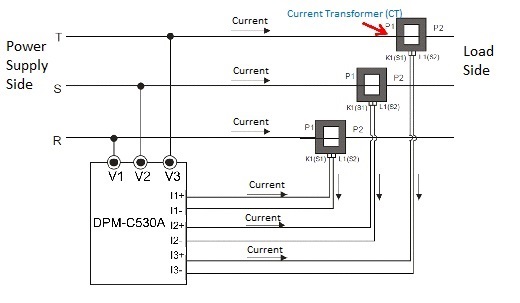
Please refer to the wiring diagram below and complete connections in accordance with the following instructions.
The primary terminals P1 and P2 are connected for the incoming primary current. The primary current enters terminal P1 and flows into terminal P2. The secondary current enters terminal I1+ of the power meter and leaves from terminal K1 of the CT, and then flows into terminal I1- of the power meter through terminal L1 of the CT. Following the current flow direction as shown by the arrows in the wiring diagram below, make the connections of terminals I2 and I3 to complete the wiring between the CT and the power meter, and give a three phase power supply to the supply circuit.
