Can Delta's 4-Line Text Panel HMI with Built-in PLC TP04P be connected to an RTU-485 for I/O extension?
TP04P and all Delta text panel HMIs that support the RS-485 communication function can be connected to an RTU-485.
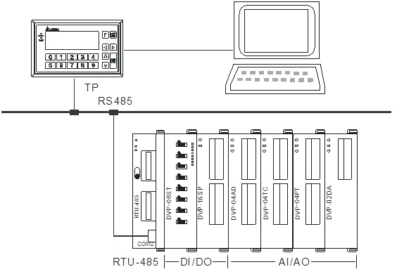
For example, there are two RS-485 communication ports on TP04P, which are COM2 (PLC mode) and COM3 (TP mode). The following section demonstrates how to send Modbus commands to RTU-485 under the TP mode to achieve remote I/O control.
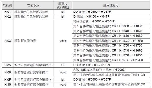
*Note: The TP display device only supports function codes for reading the input status of a bit device (H’02), reading a register (H’03), writing single datum into a bit device (H’05), and writing single datum into a register (H’06). It does not support function codes for reading the digital output status of a bit device (H’01), writing a lot of digital output data into a bit device (H’0F), and writing a lot of CR data into a bit device (H’10). RTU-485 only responds to applicable address ranges in function codes.
*Note: The TP series only executes communications on each page.
*Note: For TP04P COM2 (PLC mode) connection, please refer to the connection example in the RTU-485 Application Manual.
Application example:
This example mainly describes how the TP sends data to the RTU-485 right-side module under the ASCII mode.
 For RTU-485 setting and explanation, please see RTU-485 Application Manual.
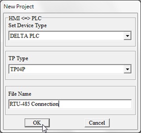
Step 1: To start a new project, select “DELTA PLC” in Set Device Type. Select “TP04P” in TP Type.
For RTU-485 setting and explanation, please see RTU-485 Application Manual.
Step 1: To start a new project, select “DELTA PLC” in Set Device Type. Select “TP04P” in TP Type.
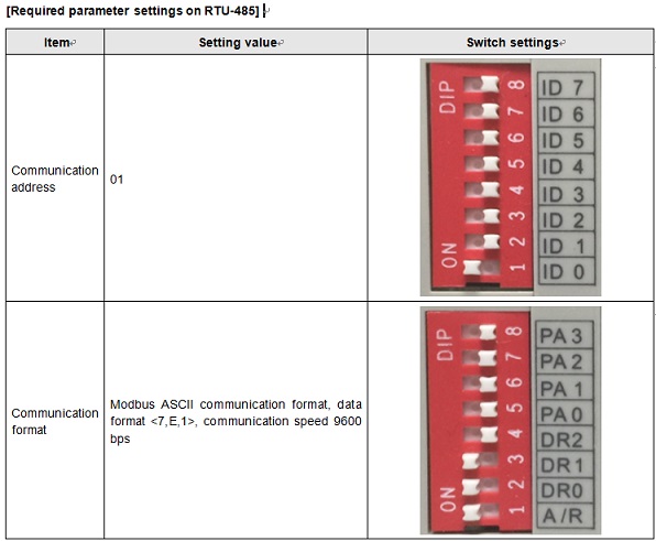
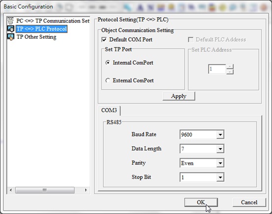
 Step 2: Select a comunication protocol. In Tools > Basic Configuration > TP PLC Protocol, set the communication of COM3 as <9600, 7, E, 1>.
 Step 3: Select a device. Drag a suitable size image in the programming area, and set related communication parameters. For example, to display the X0 input status of the current extension module DVP08ST, select “Bit Lamp Setting” first, draw the device, double click on the device, and finish settings as in the instructions below.
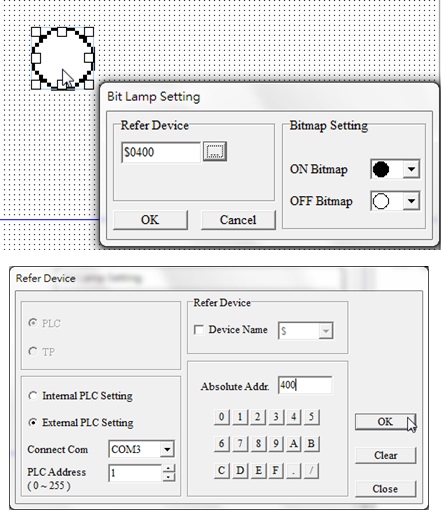 RTU-485 supports the devices shown in the table below. According to the table, the input address of X is from H’0400~H’047F. The first DI/DO device of RTU-485 is DVP08ST, the corresponding address of X0~X7 H’0400~H’0407.
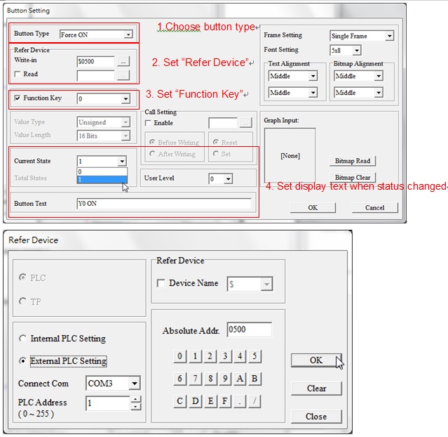
 Step 4. Control the Y point output of the DI/DO module with the “Button”. For example, to control the Y0 point in the second DVP16SP in the application, whose corresponding address is H’0500, the setting is as follows. Note that if the read function of the refer device is selected, a time out will show up during communication. When the TP sends out the command H’02, it is beyond the reading addresses of RTU-485 and will not respond to it. (The range is between H’0400~H’047F.)
 Step 5. To read registers of a special module, select “Numeric/ASCII Display”. For example, to display CR0 in the extension module DVP04AD, select the “Numeric/ASCII Display” function and draw a suitable image size, and set a refer device as in the steps below.
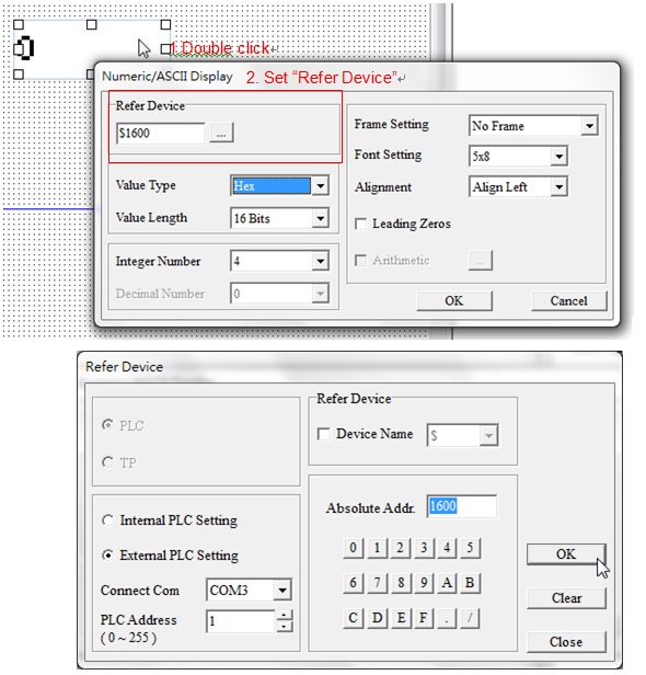 Refer to the areas of special module form in Chapter 4.2 of the user manual. The CR address of the the first special module is H’1600~H’1630. The CR0 address of DVP04AD, the firstt special module in the application, is H’1600 according to the form.
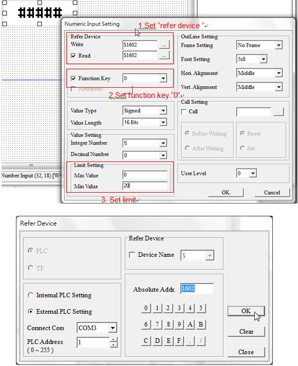
Step. 6: Select “Numeric Input Setting” to write data into register. To set CR2 of DVP04AD, drag the image in the same approach as above and follow the below setting. Write in the CR2 address H’1602 in Refer Device. Set the function key as “0”, and limit setting from “0~20”.
Refer to the areas of special module form in Chapter 4.2 of the user manual. The CR address of the the first special module is H’1600~H’1630. The CR0 address of DVP04AD, the firstt special module in the application, is H’1600 according to the form.
Step. 6: Select “Numeric Input Setting” to write data into register. To set CR2 of DVP04AD, drag the image in the same approach as above and follow the below setting. Write in the CR2 address H’1602 in Refer Device. Set the function key as “0”, and limit setting from “0~20”.
 Follow the steps above to complete communication settings for the TP series and RTU-485.