How do I set up a PLC-Link communication in WPLSoft?
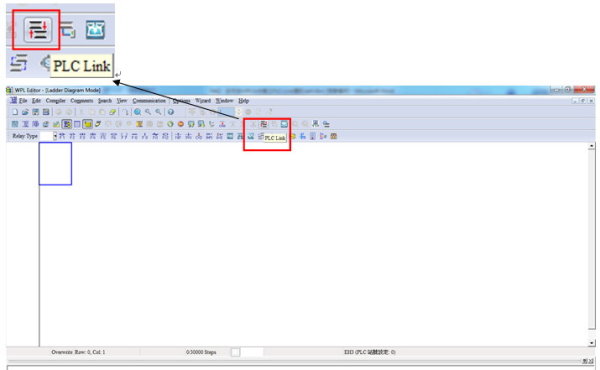
Step 1: Set parameters to complete the handshaking function of master and slave stations with the PLC-Link Wizard that is built-in to WPLSoft. (The PLC Link icon is shown in the red square in the screen shot below.)
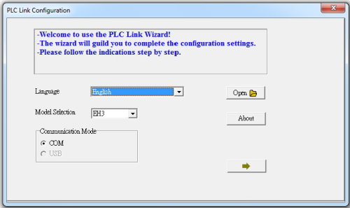
Step 2: Set PLC Link Configuration
2.1 Language: Select language
2.2 Model Selection: Select applied PLC model
2.3 Communication Mode: Select communication mode between PC and PLC
2.4 Open: Open Profile
2.5 About: Check PLC Link version
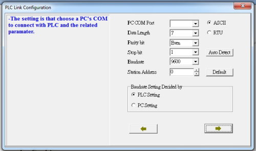
Step 3: Set a PC’s COM to connect with a PLC and the related parameters.
3.1 Baudrate Setting Decided by PLC Setting: Baudrate is set according to COM1 Port in the PLC.
3.2 Baudrate Setting Decided by PC Setting: Baudrate is set according to PLC Link Wizard.
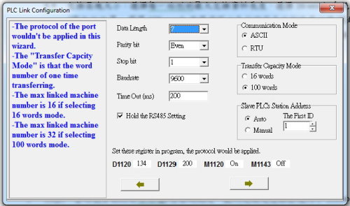
Step 4: Set Communication Mode and Transfer Capacity Mode
4.1 Hold the RS485 Setting: After selecting, RS485 communication setting should not be changed when the PLC is operating.
4.2 Communication Mode: Select ASCII or RTU communication mode.
4.3 Transfer Capacity Mode: Select max word number of one time transfer.
16 words: System will automatically set R/W position from D1480.
100 words: Users can set R/W position randomly.
4.4 Slave the PLC Station Address:
Select Auto: 32 stations are named in a sequence from the first ID.
Select Manual: Users can name the station IDs randomly.
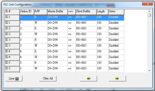
Step 5: Check the R/W settings of Masters stations (Screen shot below is an example of
Transfer Capacity Mode: 100 words / Slave PLCs Station Address: Auto)
Step 6: Set parameters of the handshaking functions of the slave station.
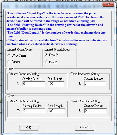
6.1 Linked Model Type: Select “DVP Series” when slave stations are DVP PLCs. Select “Others” when slave stations are other MODBUS devices.
6.2 Linked Model Status: Disable/Enable communication functions with local station.
6.3 Station Address: Station ID of slave stations.
6.4 Read-Master Parameter Setting: Set Starting Device and Data Length for the master station.
6.5 Read-Slave Parameter Setting: Set Starting Device for slave stations.
6.6 Write-Master Parameter Setting: Set Starting Device and Data Length for the master station.
6.7 Write-Slave Parameter Setting: Set Starting Device for slave stations.
7 Check Linked Machine Status
7.1 Synchronic R/W: On/Off Synchronic R/W function
7.2 Linked Times: On/Off auto shutdown of communication functions after certain times when the link receives communication errors. The times are editable.
7.3 Start Monitor: Start linked machine monitoring.
7.4 Set Parameter: Set all the settings

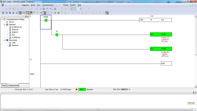
8 To automatically enable PLC-Link, set the program to function automatically after the master station starts for 3 seconds.